Complete configuration and user manual to protect your network with OPL Web Smart Switch Loop detection and Port Isolation Configuration to prevent from looping issue. Port isolation protect your data from unauthorized access from the connected client with the same switch.
OPL Web Smart Switch Loop detection and Port Isolation Configuration.
OPL RPoE-WM-2U-AG switch is 8 port web smart switch with reverse PoE function. To know more about reverse PoE function see here. In this switch 2 Uplink and 6 normal with PoE in power function with semi-managed. OPL RPoE-WM switch comes with Loop detection, port isolation, VLAN configuration and many other semi-management features which required for network management.
- Popular Post: How to Connect Any Wi-Fi without Password from Mobile?
- The 5 Important Tools for Design, Installation and Manage Fibre Networks
This post I will describe OPL RPoE-WM-2U-AG Loop Detection and Port isolation configuration to protect your network from looping and network data sharing protection.
What is Loop Detection Feature in Managed Switch?
Loop Detection and Loop prevention feature detect the looping issue in the network and shut the port getting loop issue. Loop detection configuration should be always enabled to prevent your network from the looping issue. It is a feature always on to help remove the loops from the network and keep network always up.
The Loop Detection Configuration in OPL Web Smart Reverse PoE Switch.
In OPL managed switch Loop detection feature and loop prevention feature available. In one time we can only enable one feature from loop detection and loop prevention.
Loop Detection:
If Loop detection is enabled then switch disable the same port when any looping issue comes. After disable it check the according to time we have set for interval and recover the port time.
Loop Prevention:
Prevention means before any loop comes it regularly checks the port for any issue as per time set in settings.
Read More:
- How to setup QoS to set internet Speed limit for WiFi User
- How to use WhatsApp without Phone Number with Tricks (2018)
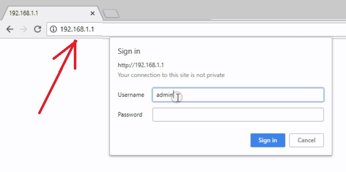
Login OPL Web Smart Switch.
OPL default IP Address: 192.168.1.1
Configure the Laptop or Desktop LAN IP with same series (Ex 192.168.1.10)
See here how to configure Laptop / Desktop LAN IP
OPL default username/password – admin/admin
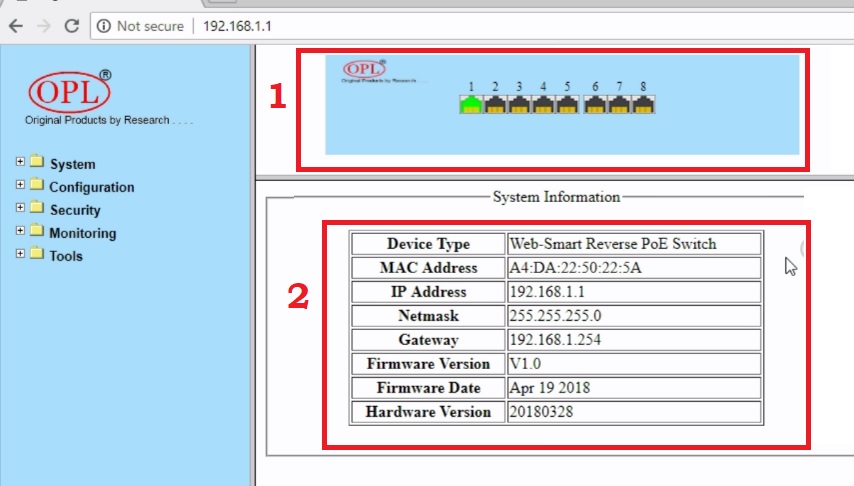
After Login switch will open in Status page.
- Physically connection status on switch pots.
- System information- this will show Mac Address, IP Address Firmware version, and Hardware version details.
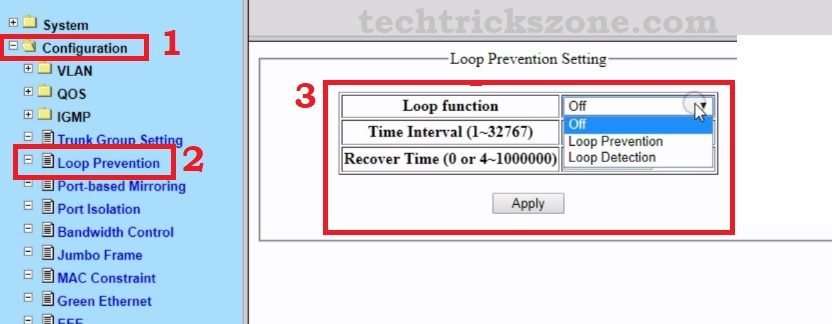
Enable Loop Detection Feature now. Go to
- Configuration
- Loop Prevention
- Loop Function: choose the Function you want to configure.
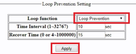
Loop Prevention Configuration.
Loop Function – Loop Prevention
Time Interval: 1-32767 (this time will use them for interval while checking loop issue)
Recover Time: 0 or 4-1000000 (this time use to recover the loop issue in case any loop detect in networks)
Press the Apply button
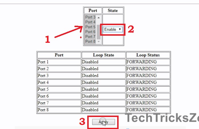
After enabling loop prevention you will get all port list with the current status.
- Port: Select the port you want to enable Loop prevention.
- State: Enable – choose to enable state
Apply: press Apply button to enable settings.
Enable save the setting under Tools from the Left side menu.
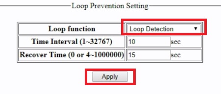
Loop Detection configuration web smart switch
Loop Function: choose Loop detection
Time interval – set the time for an interval to check loop issue.
Recover Time– Set time for recovery during loop detection in the network.
Press the Apply button and Save the settings from Tools option from Menu.
After enabling looping function your network will not affect due to any looping occur in networks. The port creates any loop will auto shut until loop removed from the networks.
The configuration of Loop feature is same for any brand managed switch such as Netgear web smart switch, D-Link web smart switch, TP-Link smart switch. The function is same to detect and remove any type of looping from network and network let down network due to loop issue.
Read More:
- 5 Best L3 Managed Network Switch for Small and Large Network (2018)
- The 15 Best Wireless Range Extenders to Boost WiFi signal [Updated]
OPL Web-smart Switch Port Isolation Configuration
Port isolation also one of the best feature of any smart switch to protect un-authorize network access with connected in the same switch.
What is Port Isolation?
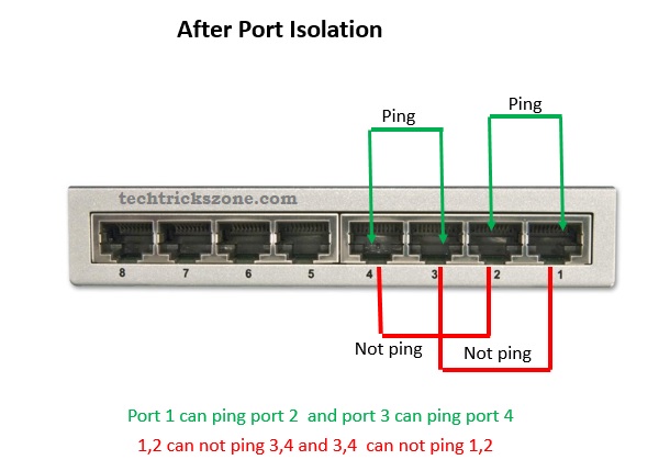
Port Isolation also called a private VLAN. It restricts the port access from other port with isolation enable. We can configure the port isolation with each port we want to restrict from any particular port.
EXP: We can set Port 1 Can access Port 2 to port 8 but port 2 to 8 cannot access each other.
Use of Port Isolation?
We can isolate port to share the network with each other. We can restrict client connected to port cannot access each other network it will help to protect the local data. For ISP port isolation can use to distribute multiple clients with the same switch with protecting the access of each other networks.
To enable port isolation to follow the steps below.
Go to Configuration – Port Isolation
Port Isolation Settings
Port – select the port for isolation
Port Isolation List- choose the port you want to share access with
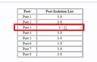
EXP: in pic port 3 select to share with port 4.
Means 3 can only access port 4.
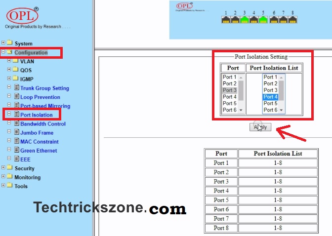
After select both port press Apply button.
See in the below list port 3 select with port 4
After confirming all port isolation settings press Save button under Tools in the left side menu.
The switch will reboot and few second to save all settings. After that, you can use OPL RPoE managed switch in networks. This basic feature of OPL Web Smart Switch Loop detection and Port Isolation will help you to fault finding in the network and ensure your data protection with sharing with each other user connected with the same switch.
Buy OPL Reverse PoE Switch Online Now with 50% Instant Discount
Related Post
- Protect Network and Wireless Devices from Lighting and Thundering
- The 10 Best VPN for Windows 10, Mac OS, Android and iOS [Free and Paid]
- The 5 Important Tools for Design, Installation and Manage Fibre Networks
Video for OPL Web Smart Switch Loop detection and Port Isolation Configuration
Video Loop Detection configuration
The post OPL Reverse PoE Web Smart Managed Switch Configuration. appeared first on .
from https://ift.tt/2nYKZAQ
Nice Blog Post thanks for sharing it.
ReplyDeleteHow to set up Netgear router
Netgear genie error
very helpful! Here you will get all kind of solution like
ReplyDeleteadmin d link
dlink setup page
D-link Support Number Australia